Engine


Start
Chassis
Body
Gearbox
Engine
Assemble
Links
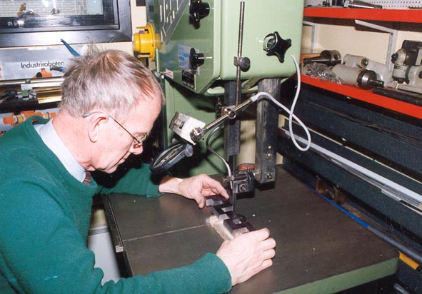
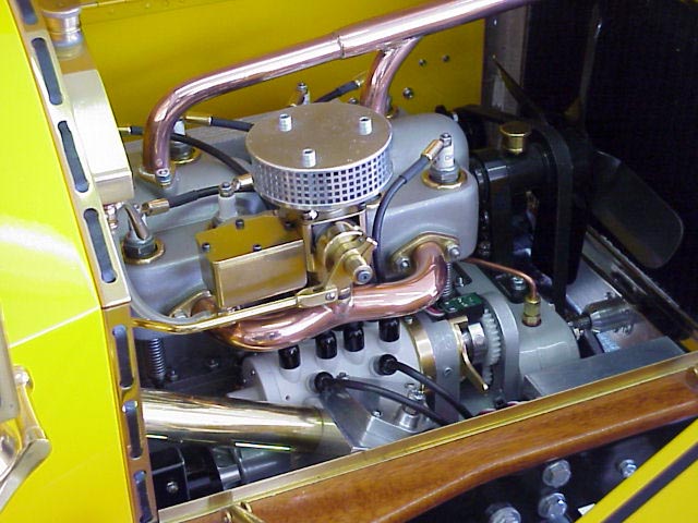
With the chassis and body finished it was time to continue with the engine. The pictures in my books did not tell me enough about the internal design of the engine so I was somewhat worried when I suddenly got the October 1994 issue of the S.I.C.-magazine from U.S.A. in my hand. / Strictly Internal Combustion - Miniature Engine Design and Construction /. (See link on last page !)

Robert Washburn the editor of S.I.C. had visited Edgar L. Roy in Boston in 1989 looking at his famous collection of seven models of the "real world antique autos". This ended up with Robert publishing drawings of Edgar L. Roy´s 1/6th scale Simplex engine.

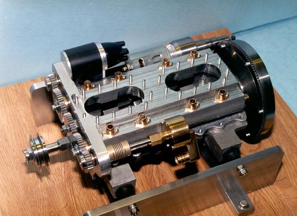
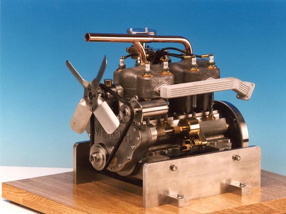
I don´t know the historical facts but the Mercer engine looks very much like the Simplex engine and the S.I.C. drawings gave me something to work from.

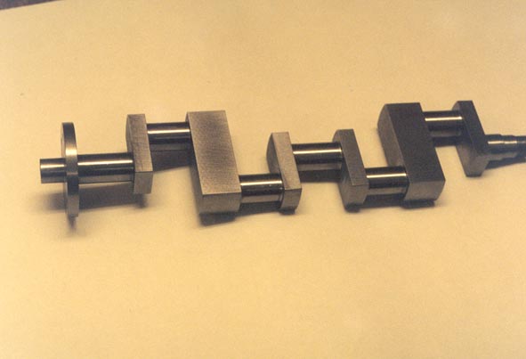
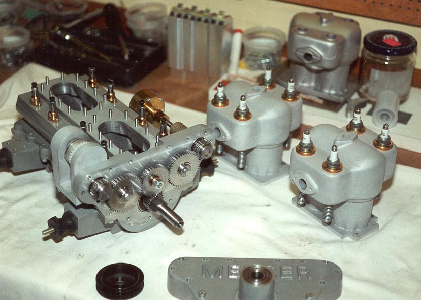
Scaling down the Mercer engine to 40% of the original size would have meant 320 cc from the 5 litre original. I decided to stop at 120 cc as I was by no means aiming for speed records with my Mercer !

J.03 Sågning av vevaxel.jpg (62465 byte)

I started making the crank-shaft by splitting a steel-bar of 10 kg ( 20 lbs) in my bandsaw. After milling with a fly-cutter I used my surface-grinder from two 90-degree angles. After marking one side it was brought back to the bandsaw.

J.04 Svarvning av vevaxel.jpg (67569 byte)


The crankshaft in my lathe.

J.05 Färdig vevaxel.jpg (27734 byte)


The finished crankshaft. Weight reduced from 10 kg to 800 grams.

K.06 Vevhus, bearbetning.jpg (86745 byte)

The patterns for the crank-case offered a most interesting job. With the castings in my hand I could start machining them in my mill. The upper and lower part of the  crankcase as well as the gear-cover were then assembled and fixed onto a carefully ground baseplate on top of two parallell blocks and fixed in the lathe. After arboring for the crank-shaft I fixed the gearcover and arbored the front bearing seat.

Then the upper two parallell blocks were removed and I could move on to boring the holes for the camshafts. In the picture above I am boring the holes for the distributor.

L.01 Kamaxelslipmaskin.jpg (40486 byte)

With the inspiration from many good ideas presented in the S.I.C. magazine I constructed a camshaft-grinder. It was applied to my tool-grinding machine where I in a most comfortable way could make three (!) camshafts. I chose SIS 2940-03 /Swedish standard/ a material made for nitro-carbonization which will help me harden the camshafts without risk for distortion.

L.03 Kamaxel i slipmaskin.jpg (80943 byte)


Grinding the areas between the cams in my tool-grinder.

L.09 Motor under montering.jpg (61316 byte)


Assembling the engine.

P.03 Motorn monteras.jpg (86278 byte)

It took me one whole year from start to finish to make the cylinder blocks. Here they are ready for assembling to the crank-case.

P.05 Mercermotorn monterad.jpg (51561 byte)


  The  engine  finished  and ready for  the chassis.

P.08  Mercer engine front view.jpg (44578 byte)


Front view of the Mercer engine

P.14 Mercermotorn, närbild.jpg (173576 byte)


Close view of the Mercer engine.


The Mercer engine has now  been successfully started.

/May  2001/


It did take some time as there had to be changes to the ignition system.  From the beginning the idea was to use a single ignition system.  This proved however insufficient and  I  had to develop a complete double ignition system.

This was made with  the help of  two  new  " RUNTRONIC"  systems  which  replaced the  earlier  "Hall type" single ignition system. The two sensors were put  180 degrees apart, close to the rotating small magnets.  By means of a rotor and two high tension   leads  the sparks were  distributed  - two at a time -   to each cylinder.   

The pictures below will clearly show  how it all was done !


095Mercernsnyatändsystem3.jpg (75061 byte)

  Picture of the engine-room with the newly installed double ignition system.

096Mercernsnyatändsystem2.jpg (67254 byte)


A closer picture of the new system


097Mercernsnyatändsystem1.jpg (64356 byte)


A still closer picture where the the high tension leads from the two  "Runtronic"  systems and the upper sensor (green) is visible.

In due time the engine will be removed from the chassis and put back into the lathe where all  further adjustments,  for running the engine smoothly, will be done.

After that it will be time to drive the Mercer-model with it´s own engine using the radio-controll system !